SMT Nuts Explained: Why More Engineers Are Moving Away from Clinch Nuts for Thin-PCB Fastening
2026.10.13
In today’s world of increasingly thin PCBs and densely packed components, hardware engineers often face a difficult trade-off: clinch nuts can easily deform thin boards, while manual nut fastening is slow and inconsistent. Especially when PCB thickness drops to 0.8 mm or even lower, the limitations of traditional clinching become obvious. SMT nuts allow fasteners to go through pick-and-place machines and reflow ovens just like resistors and capacitors, directly forming a reliable threaded connection point on the board surface. But they are not “place and forget” components. Reliability depends on the coordinated design of solder pads, solder volume control, reflow profile, and the fastening scheme. This article explains SMT nuts from principle and comparison to selection and process control.
Why Is Fastening on Thin PCBs Becoming More Difficult?
Traditional PCB fastening mainly relies on clinch nuts or rivet nuts. Both require through-holes and rely on mechanical interference or deformation to lock in place. On medium-thick boards of 1.6 mm or more, they perform stably. But when board thickness drops to 0.8–1.0 mm, clinching force can easily deform the board, and even a slight mismatch between pilot-hole accuracy and clinching force can cause yield fluctuations. At the same time, high-density PCBs leave less and less space for fasteners, and the consistency of manual fastening struggles to meet volume production requirements.
SMT nuts take a completely different approach: the fastener no longer relies on a through-hole and mechanical interference. Instead, it is soldered to pads on the board surface, and the threaded connection point is integrated directly into the standard SMT process. This means structural fastening can be completed in one pass during reflow soldering, without additional back-end assembly steps.
What Are SMT Nuts and How Are They Placed?
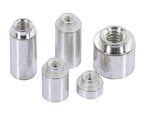
An SMT nut is a PCB fastener designed specifically for surface-mount processes. It is usually made of brass or free-machining steel, with tin plating to ensure solderability. Its bottom has a locating step that aligns precisely with the PCB pad, forming a stable internal thread connection point after reflow.
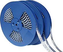
The assembly flow is straightforward: tape-and-reel-packed nuts are picked up by the pick-and-place nozzle, placed onto PCB pads, and then run through the reflow oven. The solder melts and wets the surfaces, firmly fixing the nut to the board. The entire process requires no manual insertion and is fully compatible with existing SMT lines. Solderability is referenced to IPC/JEDEC J-STD-002, and solder joint quality is judged according to IPC-A-610.
How Does It Compare with Clinch Nuts?
The core difference between the two is not thread size, but assembly sequence and load-bearing substrate. SMT nuts serve PCB-level fastening and automated placement, while clinch nuts are better suited to sheet-metal or chassis structures. If a sheet-metal solution is forced into a PCB process, problems often appear later in process flow and strength.
| Dimension | SMT Nut Clinch Nut
| Primary substrate | PCB Sheet metal / chassis parts
| When it enters production | Pick-and-place and reflow stage Stamping / post-assembly stage
| Automation method | Tape-and-reel + pick-and-place Clinching equipment + fixture
| Thin-board adaptability | Good; no through-holes needed Fair; thin boards deform easily
| Volume consistency | High; follows standard SMT flow Clinching/manual dependent
| Typical applications | High-density thin boards fastening Sheet-metal parts, chassis structures
An important detail: if the fastening point is PCB-level and you want it to go through SMT and reflow, an SMT nut is the more reasonable choice. If the fastening point is on sheet metal or a chassis, a clinch nut is usually more suitable. The two are not replacements for each other; they serve different application scenarios.
What Determines the Reliability of an SMT Nut?
Many engineers ask: is the strength of an SMT nut determined only by the nut itself? In fact, the nut base, solder pad, solder volume, PCB copper foil, and board thickness together determine the final mechanical performance. Pad lift, annular cracking, or solder joint fracture during fastening are often not caused by insufficient nut strength, but by problems in the entire load path—torque travels from the screw into the nut base, through the solder joint and pad copper, and finally concentrates in the PCB laminate.
This means the strength of an SMT nut cannot simply be copied from the specification table of a traditional metal nut. The reasonable approach is to validate it under actual assembly conditions: use the production screw, washer, and support structure; test tightening torque, pull-out force, and shear force; and retest after thermal cycling. The peak torque, off-axis downward force, and sudden-stop impact of the driving tool can be more damaging than the set torque itself.
From publicly available performance data, taking an M3 SMT nut as an example, under standard reflow soldering conditions, the typical push-out force is around 400 N, and torque capacity is approximately 1.0–1.2 N·m. Specific values vary with pad design and PCB thickness. During selection, actual working-condition test results should be the basis.
What Parameters Should Be Considered During Selection?
The most common mistake in selection is to order based only on thread size. In fact, the following dimensions should be evaluated together:
Dimensional tolerance and pad matching. Nut outer diameter, height, and internal thread precision must maintain matching tolerances with PCB hole dimensions. Pad coverage is usually required to reach 80% or more to ensure uniform solder joints during reflow.
CTE matching. When the coefficient of thermal expansion (CTE) difference between the nut material and FR-4 substrate exceeds 8 ppm/°C, solder joint stress cracking can easily occur during thermal cycling. Copper alloy nuts, with higher heat transfer efficiency and thermal expansion characteristics closer to FR-4, usually outperform stainless steel solutions in this dimension.
Tape-and-reel packaging and line compatibility. SMT nuts use EIA-standard tape-and-reel packaging, and compatibility with existing pick-and-place nozzles and feeder systems must be checked. Common thread sizes cover M2 to M4, with custom sizes and plating options available.
What Should Be Noted in the Reflow Process?
Reflow soldering is the key step in whether an SMT nut can be reliably fixed. In the preheat stage, the PCB needs to be heated evenly to 150–180°C, and the soak zone should be maintained for 60–90 seconds to ensure full evaporation of solder paste solvents. The peak temperature in the reflow zone should be controlled within 240–260°C, which must meet the melting requirements of lead-free solder (such as SAC305, with a liquidus of about 217°C) while preventing thermal damage to the nut plating.
Solder paste printing parameters are equally critical. Stencil aperture dimensions are usually expanded by 0.1–0.15 mm beyond the pad, and print thickness is controlled at 0.12–0.15 mm. More solder paste is not always better—an excessively thick or uneven solder layer can instead increase the risk of nut tilting and stress concentration. For small SMT nuts below M2, it is recommended to use a vision alignment system for high-precision placement and dynamically adjust nozzle downward pressure through pressure feedback to avoid solder paste collapse or nut misalignment.
Common Misconceptions:
Looking only at thread size, not pad design. Pad symmetry, copper thickness, and solder mask opening directly affect solder joint strength. Selection should be considered together with PCB design.
Applying clinch-nut board-thickness logic to SMT nuts. The thin-board adaptability of SMT nuts is completely different from clinching logic. The former does not rely on plastic deformation of the board, so its applicable board thickness range is wider.
Believing strength is determined only by the nut. As mentioned above, the solder joint, pad, and PCB laminate together form the load path. Acceptance should combine tightening torque, pull-out/shear testing, and retesting after thermal cycling.
Ignoring tape-and-reel compatibility with the pick-and-place machine. Tape dimensions and pick-up method must be checked against the equipment; otherwise, the nozzle may fail to pick up parts or placement may shift.
Applications and Trends
SMT nuts are now widely used in precision PCB applications such as wearables, industrial control boards, new energy storage, medical devices, automotive electronics, and communications equipment. In AI servers, SMT nuts are often used to secure liquid cooling modules, heat sinks, and PCB stack structures. In high-density computing environments with long-term vibration and thermal cycling, board-level fastening reliability requirements are far higher than in ordinary consumer electronics. In automotive electronics, automotive ECUs and ADAS modules have extremely high requirements for balancing thin-board space, fastening strength, and reflow window. SMT nuts have a CTE closer to FR-4 substrate, and after thermal cycling tests, solder joint crack rates are significantly lower than mechanical riveting solutions.
In high-consistency scenarios such as communications equipment, automotive electronics, and new energy control boards, SMT nuts are moving from “optional” to “essential.”
Sinhoo offers a full series of SMT nuts from M2 to M4, with tape-and-reel packaging, custom plating, and selection technical support. Solderability is referenced to IPC/JEDEC J-STD-002, and solder joint quality is controlled according to IPC-A-610. For samples or a selection table, please contact us.
Sinhoo
www.sinhoost.com

 Recommended News